About the Elements of Smart Bike Lock Circuit Diagram With all of the new IoT and smart-device technology, a smart bike-lock was bound to be invented. And naturally, I want to replicate this invention, add some cool new buttons with cool uses, and make it using half as much cashmoney$$$$ that I would buying the original device online. Some basic functions that I want this bike to half is
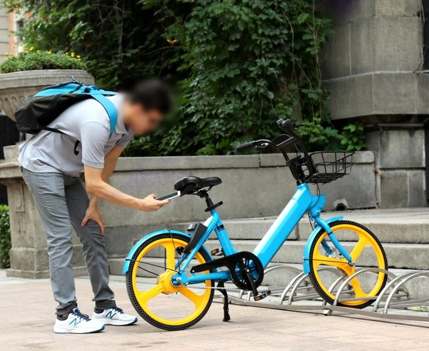
The project can be used to lock and unlock the bike remotely, as well as check the status of the lock. This project is a smart bike lock that uses an Arduino Nano 33 IoT and an ESP8266 Wi-Fi module. The Arduino Nano 33 IoT is responsible for controlling the lock and the ESP8266 Wi-Fi module is responsible for connecting to the internet.

EDGE IoT Course Project#EDGEIoT#IITJU#edge Circuit Diagram
Title: How to Build an IoT-Based Bike Lock with Arduino | DIY Smart Lock Project **Description:**Welcome to [Your Channel Name]! In this video, we'll guide y
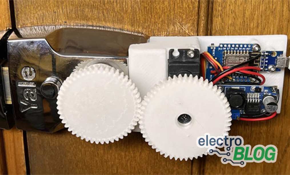
#Hooking Up the Device to Your Bicycle Lock. Once you build and run this code on your breadboard device and power the device, you should recieve a text message via Twilio when you disconnect the op amp's pin3 to ground.

Internet of Things Circuit Diagram
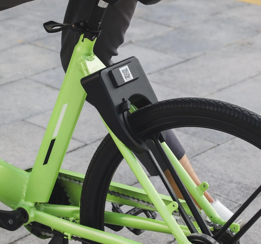
To ensure the lock could achieve its full potential continuous charging and power consumption were vitally important in the design process. Lattis wanted to make their smart lock battery last as long as possible, freeing consumers from worrying about battery life and running the risk of the lock dying, rendering it useless. "Bike locks have not changed that much in the last few decades, even though our devices have gotten far smarter, so they seem in need of an update. Designed with this in mind, the TapLock is "Unlocking innovation! 🚲🔒Discover our latest IoT project, the Smart Bicycle Lock, developed as part of the EDGE IoT course. This project demonstrates how I